
Mechanical Components for Electronic Products
Electronics & Electrical Equipment
Electronic assemblies rely on mechanical parts for support, heat transfer, connector access and protection. JUNCHU coordinates aluminum housings, mounting plates, heat-spreading parts and insulating components around your electronics layout. The project scope defines mechanical assembly and any separately specified product-level testing.
Housings · Panels
PCB & Module Mounts
TYPICAL COMPONENTS
Aluminum · Copper
Insulating Materials
MATERIAL OPTIONS
Thermal Contact
Access · Appearance
DESIGN PRIORITIES
Board Layout
Contacts · Clearances
DRAWING INPUTS
Develop the Mechanical Package
Use the board layout, connector selection and thermal concept to define the surrounding mechanical components.
Define the Envelope
Share board outlines, mounting heights, connectors and clearance to surrounding components.
Plan the Parts
Select machined, extruded or formed construction to suit the housing and expected quantities.
Check Final Fit
Review board supports, cover fit, connector openings and contact surfaces after finishing.
Protect the Assembly
Specify surface protection, identification and any handling requirements before packing.
Application Requirements
Components for Electronics & Electrical Equipment
Housings, panels, heat-spreading parts and insulating supports form the mechanical package around an electronic assembly. Review board outlines, connector cutouts and mounting heights together. Define thermal contact and grounding faces separately from cosmetic surfaces, and assign the required product validation to the appropriate project scope.
Coordinate internal space, cover fit and fastener positions with the electronics layout. Any environmental or shielding rating needs a defined test plan.
Electronics Packaging Priorities
Coordinate the housing with the electronics
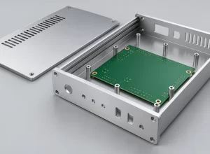
Thermal Interfaces
Define flat contact areas, mounting pressure requirements and the intended interface material. Thermal performance belongs to the complete design.

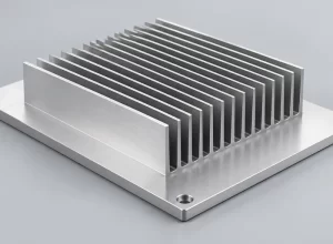
Electrical Contact
Identify grounding and bonding faces. Anodizing or coating may need masking where electrical continuity is required.
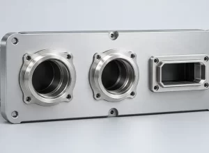
Board Clearance
Check standoff height, screw length and clearance to solder joints and components on both board faces.
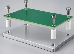
Connector Access
Use the selected connector geometry to define cutouts, cable space and installation-tool access.
Application-Specific Design & Inspection
Define the mechanical checks behind the enclosure
Keep fit, appearance, thermal contact and electrical-contact requirements distinct so each feature can be manufactured and checked appropriately.
01
Housing Construction
Compare an extruded body with machined ends, a fully machined housing or a formed enclosure using the actual geometry.
02
Heat-Spreading Faces
Specify the relevant contact area and surface condition instead of applying the same finish to the entire housing.
03
Insulating Components
Choose the exact polymer or laminate grade for load, temperature and electrical requirements; review supporting evidence where needed.
04
Contact & Masking
Mark exposed contact faces and finished dimensions before surface treatment to avoid incompatible coatings at interfaces.
05
Cosmetic Zones
Agree visible faces, texture, color and allowable marks separately from hidden mounting and internal surfaces.
06
Validation Scope
Mechanical fit checks do not establish shielding, sealing or electrical compliance. Define any such test method and acceptance criteria.
Ready To Start Your Project?
Discuss Your Electronics & Electrical Equipment Components
Include board outlines, mounting-hole locations, component heights, selected connector drawings and the enclosure assembly layout. Mark thermal contact faces, grounding areas, insulating parts and cosmetic zones. Identify the required mechanical checks and any separately specified environmental, thermal or electrical test responsibilities.
Discuss confidentiality and NDA requirements before sharing sensitive project files.