
Components for Automated Equipment
Industrial Automation
Automation parts must locate accurately, allow adjustment and remain accessible for maintenance. JUNCHU coordinates machined fixtures, sensor and motor mounts, profile frames and equipment covers around the interfaces in your machine. The drawing package connects each component to its locating surfaces, travel envelope and installation method.
Fixtures · Mounts
Frames · Covers
TYPICAL COMPONENTS
Aluminum · Steel
POM · Nylon
MATERIAL OPTIONS
Location · Adjustment
Repeatable Fit
DESIGN PRIORITIES
Datums · Clearances
Mating Interfaces
DRAWING INPUTS
Plan the Component Interfaces
Start with the assembly layout, locating datums and space needed for movement, adjustment and maintenance.
Locate
Identify the faces, dowels and hole patterns that position the component in the equipment.
Manufacture
Combine machined parts, cut profiles and formed covers around a common assembly reference.
Trial Fit
Check mounting, adjustment and clearances against the agreed mating-part information.
Identify
Mark matched or replacement parts where specified, and pack to protect locating surfaces.
Application Requirements
Components for Industrial Automation
Fixture plates, sensor mounts, profile frames and guides connect to different references in an automated machine. For each part, identify the locating features, adjustment travel and maintenance access. Share the relevant assembly view so mounting accuracy and clearance can be reviewed in context.
Define datums and locating features so replacement parts can be fitted repeatably. Flag press fits, dowel holes and contact surfaces in the drawing.
Automation Design Priorities
Design around location, travel and access
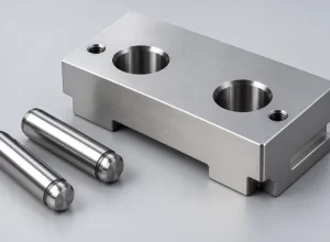
Locating Features
Dowel holes, shoulders and reference faces establish repeatable position. Relate them to a practical machining and inspection datum.

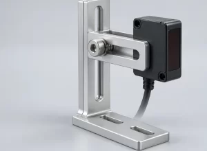
Adjustment Range
Slots and sliding mounts need clearance at the extremes of travel, with room for tools to tighten the joint.
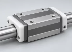
Motion & Wear
For guides and bushes, define contact load, lubrication, speed and the expected operating environment.
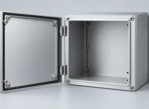
Service Access
Keep covers, cable openings and fasteners accessible without disturbing the main locating features.
Application-Specific Design & Inspection
Control the interfaces used by the machine
A fixture can meet individual dimensions and still be difficult to install. Focus the drawing and sample checks on the features that locate, move or adjust.
01
Fixture Location
Specify the datum faces and locating holes together; separate clamping features from those that establish position.
02
Sensor Alignment
Use the selected sensor body, mounting pattern and adjustment envelope to define slots, brackets and access.
03
Motor Mounting
Check bolt patterns, pilot diameters, shaft clearance and the surrounding space before releasing a mounting plate.
04
Frame Connections
Machined profile ends and connector interfaces should support the intended frame alignment and assembly sequence.
05
Replaceable Wear Parts
Select polymer or metal grades around the actual contact pair. Moisture and temperature can change a close running fit.
06
Revision Continuity
Keep an approved component revision and mating-part reference for repeat orders and future replacement parts.
Ready To Start Your Project?
Discuss Your Industrial Automation Components
Include locating datums, mating hole patterns, sensor or motor references, adjustment limits and the surrounding movement envelope. Identify wear parts, replacement quantities and the sample checks needed to confirm installation. State the approved drawing revision, material, finish and quantities for each item.
Discuss confidentiality and NDA requirements before sharing sensitive project files.