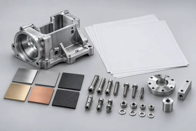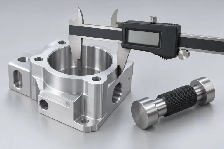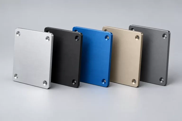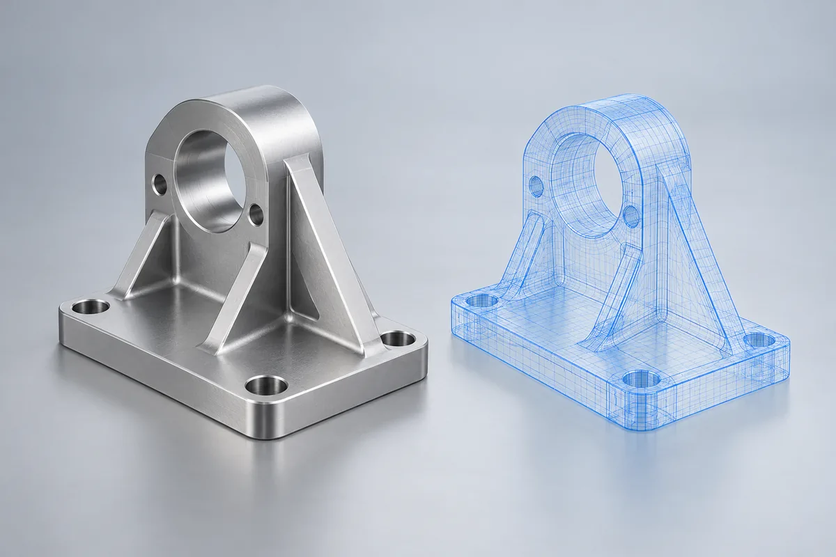
Pair the model with a drawing. A STEP or IGES model communicates geometry. A dimensioned PDF communicates the revision, datums, tolerances, material, finish and requirements that may not be contained in the model. Resolve discrepancies between the two.
- Use the same part number and revision across the model, drawing and bill of materials.
- Identify critical fits, thread standards, usable thread depth and surface roughness on functional faces.
- For sheet parts, include material thickness and the formed geometry; a flat pattern may need adjustment for production tooling.
- For profiles, include the section, cut lengths and secondary machining.
- For assemblies, include mating parts, hardware and the required checks.
Make the commercial scope clear. State prototype and likely repeat quantities, finish, required records, shipping destination and target date. Identify which features can change if an alternative route reduces complexity.
If CAD is incomplete: send a sketch, photo or functional description to start the discussion. Identify the dimensions that are known and those requiring definition before quotation.
File checklist: part number; revision; model; PDF drawing; BOM where applicable; quantity; finish reference; inspection requirements. Prepare a project enquiry.
Check the package before uploading
- Use one identifiable part number and revision for each controlled model and drawing.
- Confirm units and make clear whether the model represents the finished or pre-treatment geometry.
- Include thread standards, functional datums and dimensions that cannot be inferred from the model.
- For assemblies, provide a BOM and identify supplied hardware and mating components.
- List unresolved items in a short note rather than leaving contradictory values in different files.
If a dimensioned drawing and a model disagree, identify the governing requirement before manufacturing. Do not assume a mesh file communicates precision tolerances or a controlled thread specification.